Big Trouble In Little Blender – 1.7 Initial Unity FBX Import & Animation Notes (Part2)

blender-socket

Notes made after creating a spring for a game element in my current Unity project.

I’d built a model and animated it in Blender using rotation, location and scale – no armatures required. I wanted to be able to import the model into Unity with the multi-mesh animation all ready to go. These notes are based on the mesh having only one animation

These notes probably won’t be useful for anyone other than myself. I’m planning on building models as required, rather than in one lump – Which means I’ll forget everything in the meantime & have to relearn every model I build – To avoid this as much as possible, I’m hoping to use these posts as a reference point.

Apologies for any obvious mistakes or omissions – These notes were made as I was learning, and not necessarily as I had learnt.


Exporting a mesh with a single animation created using rotation /scale and location – Using no armatures.

Important safety tip:
when creating animations this way –
if the ‘scale’ of a mesh is modified during the animation
the scale of all child meshes will also be affected
this will only be apparent after importing into unity
the animation will play as expected in blender.

1.1 Animation Without Armature

First step – change layout to ‘Animation‘ (top of the window, right of the help menu)

1.2. Goto animation layout

change the view in the top left frame from dope sheet to ‘Action Editor

1.3 view action editor

in the ‘Outlier‘ frame on the far right, select all the meshes with animations you want to merge

1.4 select all animated meshes

Back in the ‘Action View‘ frame (top left) – click ‘+ New‘ button to create a new ‘action’ – this will merge the animations of the selected meshes into one action

1.5 click to create merged animation
Blender will be give this the default name ‘Action

1.6 New animation called action

Click the F button – Positioned next to the Action section

1.7 Press F

Looking something like this;

1.8 looks something like this

Now the action has been created – it needs to be exported to Unity (in this example I’m exporting as an as an FBX)

Select File->Export->FBX

1.9 when exporting the fbx

This will display the ‘export FBX‘ options frame
In this section – Select ‘Animation‘ & untick everything except ‘Baked Animation

1.10 turn off everything except baked animation

Next – in the ‘Armatures‘ section – clear the ‘Add Leaf Bones‘ tickbox

1.11 no armature so untick leaf bones

in the ‘Main‘ section – make sure only mesh is selected (Empty, Camer, Lamp, Armat & Other should be deselected)

1.12 only the mesh needs to be exported

& Finally – Click the ‘Export FBX‘ to export and save the model into the Assets folder in your Unity project.

When the model is opened in Unity – it should only show one animation (called ‘Scene‘)

01c-FullScreen-&-large-base---2-ALT---2


Last post: 1.6 Animating a basic spring

Contents page.


Big Trouble In Little Blender – 1.6 Animating a basic spring

blender-socket

Notes made after creating a spring for a game element in my current Unity project. I needed to animate the spring – The notes below provide a method which keeps the scale intact.

These notes probably won’t be useful for anyone other than myself. I’m planning on building models as required, rather than in one lump – Which means I’ll forget everything in the meantime & have to relearn every model I build – To avoid this as much as possible, I’m hoping to use these posts as a reference point.

Apologies for any obvious mistakes or omissions – These notes were made as I was learning, and not necessarily as I had learnt.


In the add modifier section change the value of the ‘Screw‘ field to stretch the spring to the desired maximum height.

1.1 spring streched

next duplicate the spring using tools->duplicate – creating spring #2

1.2 duplicate button

Back in the add ‘Modifier Tools‘ section – change the ‘Screw‘ value of this duplicate so the spring #2 is at its minimum desired height – then click ‘Apply

1.3 duplicated minimum height

Select the original (fully expanded) spring #1 and click ‘Apply‘ in the ‘Add Modifier‘ box

1.4 Click apply


With the original (fully expanded) spring #1 – still selected

1.5 Select original spring

select ‘data object data‘ – the triangle icon next to the modifiers screwdriver icon

1.6 data object properties

in the ‘shape keys‘ section of ‘data object data

1.7a shape keys

click the + button/icon
this should add an element called ‘Basis
storing the settings the original (fully expanded) spring #1

1.7b shape keys

Select the second (fully contracted) spring #2
hold down shift and select the original (fully expanded) spring #1

1.8 both springs selected

in the ‘shape keys‘ section of ‘data object data
click on the black arrow/triangle (under the ‘add button‘)

1.9a black arrow down
this should display a pull down menu
from this menu select ‘join as shapes

1.9b join as shapes
which will add a second element to the ‘shape keys list‘ – this element will have the name of the second (fully contracted) spring #2 (in this case Vert.001)

1.9c second spring added

Since there no further need for the second (fully contracted) spring #2
this can be hidden (or deleted)

1.10 second spring hidden spring


In the ‘shape keys‘ section of ‘data object data
click on the name of the second (fully contracted) spring #2 (vert.001)

doing this should expand the ‘data object data‘ section
displaying more the shape keys parameters
(if this doesn’t occur try clicking on the white down arrow on the right hand side of the ‘data object data‘ section

1.11a second spring entry
sliding the ‘value‘ parameter up and down should expand and contract the spring.

1.11b spring value 0
Value 0 = Maximum
1.11c spring value 0.5
Value 0.5 = Mid
1.11d spring value 1
Value 1 = Minimum


To create an animation – Using the animation bar move the green marker to the first frame

1.12 Frame 1

in the ‘shape keys‘ section of ‘data object data
slide the ‘Value‘ parameter and set the spring to fully coiled

1.12b Frame Added
& with the mouse pointer OVER the ‘Value‘ parameter press the I key
this will add a frame to the animation bar & turn the ‘Value‘ field green

1.12b Frame Added

in the animation bar move the green marker to the last frame
& with the mouse pointer over the value parameter press the I key

1.13 last frame

In the animation bar move the green marker to the middle frame

in the ‘shape keys‘ section of ‘data object data
slide the ‘Value‘ parameter and set the spring to fully uncoiled
& with the mouse pointer over the value parameter press the I key

1.14 Mid Frame

Now pressing play – you should have a half decent bouncing spring animation

2017-05-13-1336-49---2-ALT


Next post: 1.7 Initial Unity FBX Import & Animation Notes (Part2)

Last post: 1.5 Creating a basic Spring

Contents page.


Big Trouble In Little Blender – 1.5 Creating a basic Spring

blender-socket

Notes made after creating a spring for a game element in my current Unity project. The process itself isn’t too complicated & the results are pretty nice.

These notes probably won’t be useful for anyone other than myself. I’m planning on building models as required, rather than in one lump – Which means I’ll forget everything in the meantime & have to relearn every model I build – To avoid this as much as possible, I’m hoping to use these posts as a reference point.

Apologies for any obvious mistakes or omissions – These notes were made as I was learning, and not necessarily as I had learnt.


First the ‘Add Mesh: Extra Objects‘ add-on needs to be enabled – This is used to add a single vertices later in the process.

To do this – goto File->User Preferences

1.1 User Preferences

This should open the ‘Blender User Preferences‘ window
From here click Add-On’s tab at the top of the window and search for ‘Extra Objects

1.3 Addons

Add a tick to ‘Add Mesh: Extra Objects
& everything is done.


Next add a circle – this circle will be used by blender to create the body of the spring;

2.1 Add circle

Once created – scale the circle to the desired thickness of the spring

2.2 Scale circle

since the spring will coil around the XY axis – the circle needs to be rotated by 90 degrees on the x axis

2.3 Rotate circle

In this example – the spring will be generated/coiled around the central point (position 0, 0, 0).

The radius of the spring will be determined by how far the circle is moved along the x axis

2.4 Position circle 2


Now to add a single vert – this is used to determine the centre of the spring

Make sure the circle is selected.
Press shift-A to open the add menu
From here select – Mesh->SingleVert->Add Single vert

3.1 Add Single Vert

this will add a single vertices at position 0, 0, 0

3.2 Single Vert Added


The mesh and circle need to be ‘joined‘ creating a single object;
Go to ‘object mode‘ (bottom half of the screen – right of the Object menu)
right click the circle
hold shift and right click the single vert
this will select both elements at the same time

4.1 Both Objects Selected

hold ctrl-J – this will join the two objects
it will also move the axis point to the middle of the world (position 0, 0, 0)

4.2 Both objects joined


Next the screw tool is used to generate and define the spring – but first it is needed to create a doughnut;

On the right hand side of the screen in the click the spanner icon
this will open the modifiers section

5.1 modifiers

click ‘Add modifier

5.2 Add modifier

and from the list select ‘Screw

5.2 Add screw

this should apply the ‘Screw Modifier‘ to the circle

5.2 screw added


Construct the spring from the doughnut;

In the ‘Add Modifier‘ ‘Screw‘ settings;

6.1 screw modifier settings

to set the scale of the coil – change the value in the ‘Screw‘ section
this will determine how much the coil rises each 360 degree rotation

6.2 set scale

set the number of coils – change the value in the ‘Iteration‘ parameter
this will termine the size of the spring – the number of coils used to make up the spring

6.3 set iterations

the steps parameter determines how many angles are used to build each coil
the default is 16 – since I generally work with low poly game elements I’m moving this down to 8

6.4 steps 8

make sure ‘click order‘ option is selected to make sure the spring is drawn nicely

6.5 calc order


That should create a simple spring.
if thats all you need – click ‘Apply‘ in the modifiers box to set the values chosen & move on (maybe close the ends of the spring?)

if you want to animate the spring – DON’T click ‘Apply‘ quite yet… go to the next post (link below) and continue from there…

7.1 apply settings


Next post: 1.6 Animating a basic spring

Last post: 1.4 Initial Unity FBX Import & Animation Notes (Part1)

Contents page.


Big Trouble In Little Blender – 1.4 Initial Unity FBX Import & Animation Notes (Part1)

blender-socket

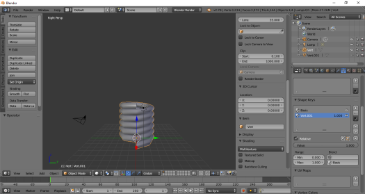
Notes made during my first attempt to play animations saved into an FBX export within a Unity project.

In blender, I’d attached bones to meshes individually – After importing the fbx into Unity, I needed to find out how to play each meshes animation simultaneously.

These notes probably won’t be useful for anyone other than myself. I’m planning on building models as required, rather than in one lump – Which means I’ll forget everything in the meantime & have to relearn every model I build – To avoid this as much as possible, I’m hoping to use these posts as a reference point.

Apologies for any obvious mistakes or omissions – These notes were made as I was learning, and not necessarily as I had learnt.

blender-import

Useful site: Play Two Animations Simultaneously using Animator

From Blender – export to fbx & save directly into assets folder of the Unity project. There are notes online stating that blender files can be used directly in Unity project – Though when using blender files, I found the initial rotations and positions of the models meshes were out of place. fbx was easier/faster for me to setup & integrate.


To configure the models animation to play in a loop:
In the project pane, click on the imported model
This should display the setting in the inspector window (right side of the window)
Select the Animations button
Ensure import Animation is ticked
In the clips section you can preview each animation.
When a clip is selected it’s settings should be displayed.
Ensure Loop Time is ticked.
This should be enough to add looping.


To play multiple mesh animations simultaneously:
e.g. I had one animation assigned to the top lip mesh, a second animation for the bottom lip mesh – To get the biting animation to work I needed to play both animations at the same time

In the project screen – create animation controller component
double click the animation controller – this should set it to the animation window

From the main pane, select animator
In the project pane; find the model you are trying to animate & click the triangle symbol next to it – expanding & displaying its contents.
Within the contents, find the first animation clip you wish to use – left click & drag this into the animator window
It should automatically have a transition from entry to the animation predefined.
(If not – right click the entry square/element, select Make Transition from the context menu then left click on the animation you’ve just added)

This should setup the animation for the first mesh. For other meshes to animate simultaneously;

In the animator window create a new layer – To do this, click on the + button on left hand side of the window.

(If the + button isnt visible – the layers pane has been hidden – on the very top left of the animator pane, click on the button with two semi-circular lines (this icon is supposed to represent a closed eye) – This should change the icon to n eyeball & display the layers pane)

Clicking on the + button will create the new layer & set the animators focus to the newly created layer (click on the new layer to be sure).
From the project pane, find the model (click the triangle to expand its contents if necessary), select the animation clip for the next mesh you want to add – left click & drag this into the animators main window.

As before, Unity should automatically create a transition from entry to the animation.
On the left hand side of the animator’s window, from the list if layers, left click on the cog icon for the newly added layer & set it’s weight to 1


Now we have the model imported & the animation controller component animated – We need to create a prefab of the imported model for use in-game.

To create the prefab: left click and drag the model from the project pane into the hierarchy pane. Then left click and drag the model from the hierarchy pane back into the project pane – a prefab should be created with the same name as the imported model (the instance in the project pane can be deleted).

To animate the prefab: In the project pane, left click the prefab – This will display it’s settings in the inspector pane. In the inspector pane, expand prefabs animator component (add an animator component if one does not already exist). From here we need to populate the Controller and Avatar fields.

To populate the controller field: In the project pane, find the animation controller component, left click and drag this into the controller field of the prefabs animator component.

To populate the Avatar field: In the project pane, find the imported model, click the triangle to expand its contents, look for an element called xxxAvatar entry (e.g. for the mouth mesh, this was called the mouthAvatar – Its icon is a torso & head) – Left click and drag this into the prefabs->animators->avatar field.

This should add the animation to the prefab ready for use in-game.


Next post: 1.5 Creating a basic Spring

Last post: 1.3 Initial Animation Notes

Contents page.


Big Trouble In Little Blender – 1.3 Initial Animation Notes

blender-socket

Notes made during my first attempt a Animating on Blender.

These probably won’t be useful for anyone other than myself. I’m planning on building models as required, rather than in one lump – Which means I’ll probably forget everything in the meantime – To avoid that as much as possible, I’m hoping to use this as a reference point – Allowing me to learn new tools & features of blender; rather than constantly relearning the same tools.

Apologies for any obvious mistakes or omissions – These notes were made as I was learning, and not necessarily as I had learnt.

blender-animation

Useful site: Beginning Blender Tutorial: Animating and Rendering a Mushroom

Basic animation can be managed in default view.

First add an armature – This will hold a set of (1+) bones
Mesh Tools panel->create->armature
or shift-A ->armature->single bone

With the armature selected (left click in the outlier window)
In Data Object Data panel, from the row of icons/tabs at the top – select the stickman
scroll down to the display section & add a tick against Names & X-Ray
Names allows each element to have a name
X-Ray ensures the bone can be seen through the model.

Use Mode Select and switch to Edit Mode.
Use Mesh Tools ->Transform or Mesh Values -> Translate to move the bone into position

To add another bone in the chain (with the bone selected) either;
MeshTools -> Modelling -> Extrude
Or with the press E

To attach a bone to a mesh – in the Outlier panel
Drag the MESH into the Armature – The armature should be the parent

This should open the set parent to window;
Generally choose either:
Armature Deform -> With Automatic Weights (reshapes mesh on animation)
Bone – Ensure model is in a resting\start of animation pose before applying this.
For simple animations I’ve used bone.

Mode Select -> Pose Mode allows you to move/position bones.
Ctrl-Tab is the keyboard shortcut from Pose Mode (Click in the main/model window first)
Or in the Outlier panel, under the Armature in the hierarchy click on Pose

To add an animation – In the Default screen layout..
If the animation timeline is hidden – At the bottom of the screen there are two rows of icons/tabs/drop down menus – click and drag up from the middle to reveal the animation timeline

To add a frame…
In the animation timeline – left click to set the green animation bar at the desired time.
Use the bone attached to the mesh to translate/rotate/etc the mesh into the desired position for that frame of the animation.
Right click in the main/model window
Press I – This should display the Insert Keyframe Menu
From the Insert Keyframe Menu – Select the animation type – e.g. If, for this frame in the animation, the mesh had been rotated – to store the rotation – select Rotation from the Insert Keyframe Menu
This will create an animation frame at the current time position (yellow bar will be added to show the animation timeline)
Note the animation timeline will only show frames for the currently selected mesh
& repeat as required.

The length of the animation is determined by the start & end key frame in the animation timeline
Start and end fields should be clearly visible in the animation bar.
24 frames = 1 second
If the animation ends after 12 frames (30 seconds) – set the start to 0 & the end to 12

Frames cannot be moved, but can be deleted.
To delete – Highlight the frame in the animation timeline (left click over the frame to be deleted – this should move the green bar over the yellow bar) & press space
Then click delete keyframe (twice)


Next post: 1.4 Initial Unity FBX Import & Animation Notes Pt1

Last post: 1.2 Initial UV Unwrapping Notes

Contents page.


Big Trouble In Little Blender – 1.2 Initial UV Unwrapping Notes

blender-socket

Notes made during my first attempt a UV Editing on Blender.

These probably won’t be useful for anyone other than myself. I’m planning on building models as required, rather than in one lump – Which means I’ll probably forget everything in the meantime – To avoid that as much as possible, I’m hoping to use this as a reference point – Allowing me to learn new tools & features of blender; rather than constantly relearning the same tools.

Apologies for any obvious mistakes or omissions – These notes were made as I was learning, and not necessarily as I had learnt.

blender-uvunwrap-alt

Select UV editing from the Screen Layout pulldown at the top of the window – This will show uv window on left & edit window on the right.


Setup Environment:

In edit window
Select Limit Selection To Visible icon in bottom left (right of faces icon, two squares with squares for corners).
Select & drag the add window lines in the top right of the user perspective window – & pull left – this will create a new sub window…
…In this window, select the Editor Type pull-down (bottom left – cube with up & down arrow) & select Outliner.
Resize windows as required.
Ensure – show texture is active – click Viewport Shading pulldown at bottom thee window (circle icon) & select Texture.

In UV window:
On the right hand side of the window – select & drag the Grease Pencil window to the right (until it is removed from the screen).
On the left hand side – select & pull the plus tab – This will initially just show grease pencil again, however once faces have UV settings applied, it will display translate/rotate/scale buttons.
Click the UV Selection and display mode: Island icon – this is an icon with two rectangles – right one is orange – may need to resize window to make this visible.


Edit UV’s:

In edit window:
Change to edit mode – Using the Mode Select pull down menu at the bottom of the screen
Select the Selection Type – Face (icon of cube with one face selected).
Select everything (press A).
From the menu’s at the bottom of the edit window: Mesh->UV Unwrap->[select unwrap method here] – unwraps model for UV painting.

In UV window:
ALT-O – Opens file explorer to add texture.
Add texture – this will apply the same texture to all faces – Otherwise the texture will need to be reapplied for each group.

In edit window – For individual faces/groups of faces:
Change to edit mode – from Mode Select pull down menu at the bottom of the screen
Choose Selection Type – Face (icon of cube with one face selected).
Use right mouse button to select individual faces – ctrl + right mouse button multiple faces
From the menu’s at the bottom of the edit window: Mesh->UV Unwrap->[select unwrap method here] – this will unwrap the selected faces.

In UV window:
Select everything (press A) or right mouse click for individual faces.
Use translate/rotate/scale in the Mesh Tools column to move and position faces on texture
right mouse button to select faces.
– pressing translate/rotate/scale will select their faces (e.g. after pressing scale, moving the mouse will rescale the selected faces without needing to press the left or right mouse button)
– once complete click left mouse button to place/apply.


Next post: 1.3 Initial Animation Notes

Last post: 1.1 Initial Modeling Notes

Contents page.


Big Trouble In Little Blender – 1.1 Initial Modeling Notes

blender-socket


My last attempts at 3D modelling were for the XNA games I wrote – 2-3 years ago.
Back then I was using the cut-down version of SoftImage that was offered free to XNA subscribers.

I was never that skilled & what I remember is pretty patchy – So moving onto Blender has provided a steep learning curve. Fortunately the models I’m putting together a pretty simple; allowing me to learn as I build.

I’ve made some notes from my first attempt (which I’ve copied below).
These probably won’t be useful for anyone other than myself. I’m planning on building models as required, rather than in one lump – Which means I’ll probably forget everything in the mean time – To avoid that as much as possible, I’m hoping to use this as a reference point – Allowing me to learn new tools & features of blender; rather than constantly relearning the same tools.

Apologies for any obvious mistakes or omissions – These notes were made as I was learning, and not necessarily as I had learnt.


blender-edit


Useful site: Blender Reference Manual

Use default view.

Currently using the ‘Blender Game‘ rendering engine.

Mesh Create – On the left, create tab to add meshes
Mesh Tools – On the left, Tools tab to manipulate – translate, rotate, scale etc…

Outlier
On the top of the right column
This is the scene tree – showing models, animations, etc.

Mesh Values
To the left of the outlier, there should be a ‘+‘ tab
Pull this out to show specific values for mesh translation, rotation, scale, etc..
These values are only visible in ‘Edit Mode‘ (see below)
In the main modeling window:

Mouse Buttons
Left mouse button moves the 3D cursor – try not to use the left mouse button
Middle mouse button (pressed & move) – rotates the scene
Middle mouse button (scroll wheel) – zoom in/out
Right mouse button selects (e.g click on a mesh to pick up and move the mesh)

Mesh view Shortcuts
Note – to rotate around a specific object/mesh – press ‘.‘ (full stop on the number pad)
Ensure NUMBLOCK is on.

front/left/top windows are not automatically visible.
To save screen real estate – shortcuts for the main window are:
NUMBLOCK ON &
1 = Front view
7 = Top view
3 = Side view
0 = Camera view

Mode Select
At the bottom of the screen, there is a pull down menu.
When modelling there are two main modes;
Object mode: moves & positions meshes
Edit mode: edit faces/vertices/edges etc…

Selection Type –
With ‘edit mode‘ selected, at the bottom of the screen there are three icons
cube with a small orange dot – select this to edive vertices/nodes
cube with orange line – select this to edit edges
cube with one face orange – select this to edit faces/polygons

Once selected
right click to select specific edge, vertices,face
shift-right click to select multipoles edges, vertices,face, etc.
Useful Shortcuts – Press;
A – Select/Deselect everything
Z – Toggle wireframe on/off
CTRL-I – Inverse selection
K – knife tool, Used to add edges.
(use left mouse button to add nodes)
SPACE to save
GG (G twice) – Reposition a vertex.
E – Extends edge, vertices, face (whichever is selected when E is pressed)
W – With an edge, vertices, face selected this opens the ‘Specials’ menu – subdivides face/bevel, etc…


Next post: 1.2 Initial UV Unwrapping Notes

Contents page.